Airflow pattern testing is one of the key steps in qualifying the performance of isolators prior to aseptic manufacturing in compliance with GMP requirements. Verifying whether the airflow pattern meets specified standards is critical for ensuring product quality and safety.
According to the EU GMP Annex 1, detailed requirements and expectations for airflow model studies are provided:
Clause 4.4 requires that the unidirectional airflow system for the entire Grade A area (e.g., unidirectional airflow workstations within RABS or isolators) must be justified and qualified.
Clause 4.15 stipulates that the airflow pattern within cleanrooms and clean areas should be visualized to demonstrate that air does not flow from areas of lower cleanliness to higher cleanliness grades. Additionally, it must be confirmed that airflow does not originate from less clean zones (such as the floor) or from operators or equipment that may transfer contamination to higher-grade areas. Where unidirectional airflow is required, visualization studies should confirm compliance (refer to Clauses 4.4 and 4.19). When filled product is transferred through a small opening into an adjacent lower-grade cleanroom, airflow visualization must demonstrate that air from the lower-grade cleanroom does not enter the Grade B zone. Airflow pattern studies should be conducted under both static and dynamic conditions (e.g., simulating operator interventions). Videos of airflow visualization should be retained. The results of airflow visualization studies should be documented and taken into account when establishing the environmental monitoring program.
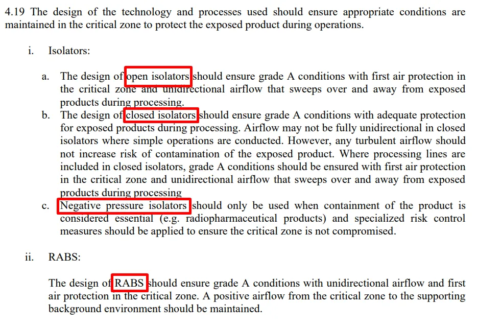
Clause 4.19 outlines airflow model requirements for various types of isolator systems. Open isolator designs must ensure Grade A conditions through first air protection at critical zones and unidirectional airflow sweeping across exposed product during operations. Closed isolator designs must protect exposed products throughout the process to maintain Grade A conditions. Complete unidirectional flow is not mandatory for simple operations, provided that it does not increase the risk to product exposure surfaces. RABS must have unidirectional airflow and first air protection in critical areas to ensure Grade A conditions. A positive pressure gradient must be maintained from critical areas to the supporting background environment.
Since airflow pattern testing can only be conducted after equipment installation, any failures during testing may result in costly and time-consuming structural modifications. To mitigate these risks, Computational Fluid Dynamics (CFD) simulations are often used in the early design stage to model airflow patterns. CFD not only helps identify and avoid potential design flaws but also assists in optimizing airflow distribution within the isolator chamber to better protect critical aseptic operations.
Airflow pattern tests typically involve two scenarios: static and dynamic conditions. In static tests, the equipment is in unidirectional flow mode and idle (non-operational), simulating routine operator interventions. In dynamic tests, the equipment is operational under normal running conditions while unidirectional airflow is active.
During the test, operators use handheld smoke tubes to release smoke above critical areas. The smoke should pass through key points, and the flow patterns are filmed against a contrasting background to clearly reveal the airflow path. The recorded video should capture the full flow sequence from smoke release through the critical point and exit from the Grade A zone, as well as detailed flow patterns at each critical point to assess potential disruptions. Each test location must be documented after completion.
Reporting:
After testing, the recorded smoke videos must be categorized and edited based on static or dynamic conditions. The test results should then be analyzed to confirm that airflow patterns provide sufficient protection during normal operations and human intervention. Based on the airflow model, locations for placing biological indicators (BIs) in the isolator system should be determined for subsequent decontamination efficacy validation. All test parameters, including equipment settings, airflow velocities, and pressure differentials, should be recorded to serve as references for future equipment operation.
3.1. Inconspicuous Airflow in Video Footage
Cause: Water mist smoke evaporates quickly and lacks color, making low-intensity smoke difficult to capture.
Solution: Increase the output of the smoke generator or switch to a more visible smoke-generating method.
3.2. Blurry or Poor-Quality Video Recording
Cause: Light reflection from multi-layered glass affects visibility.
Solution: Use a black curtain as the backdrop to reduce reflections; adjust room lighting or add supplementary lighting to enhance clarity.
3.3. Blind Spots Prevent Full Visualization of Airflow
Cause: Complex internal components create obstructions.
Solution: Add cameras at different angles to ensure full coverage.
3.4. Airflow Does Not Adequately Cover Operator Interfaces
Cause: The operational area is too large to be fully covered.
Solution: Adjust the position and height of the smoke tube; use additional smoke devices to increase coverage.
Airflow pattern testing should be reconfirmed, especially after modifications to the HVAC system, process flow, or equipment structure.
The PDA Points to Consider No.1 Aseptic Processing (Revised 2023) recommends that the requalification interval be determined based on a risk assessment of the air handling system’s design and performance capability. In the same section under “Rationale,” it is recommended that this interval should not exceed five years, and any interval longer than five years must be supported with additional justification.